BT-104 (GS) – Basic Electrical and Electronics Engineering
December 2023•COMMON•SEMESTER-2
December 2023
Max Marks: 70
Duration: 3 Hours
Instructions:
• Attempt any five questions.
• All questions carry equal marks.
Q.1
a)Unit 1
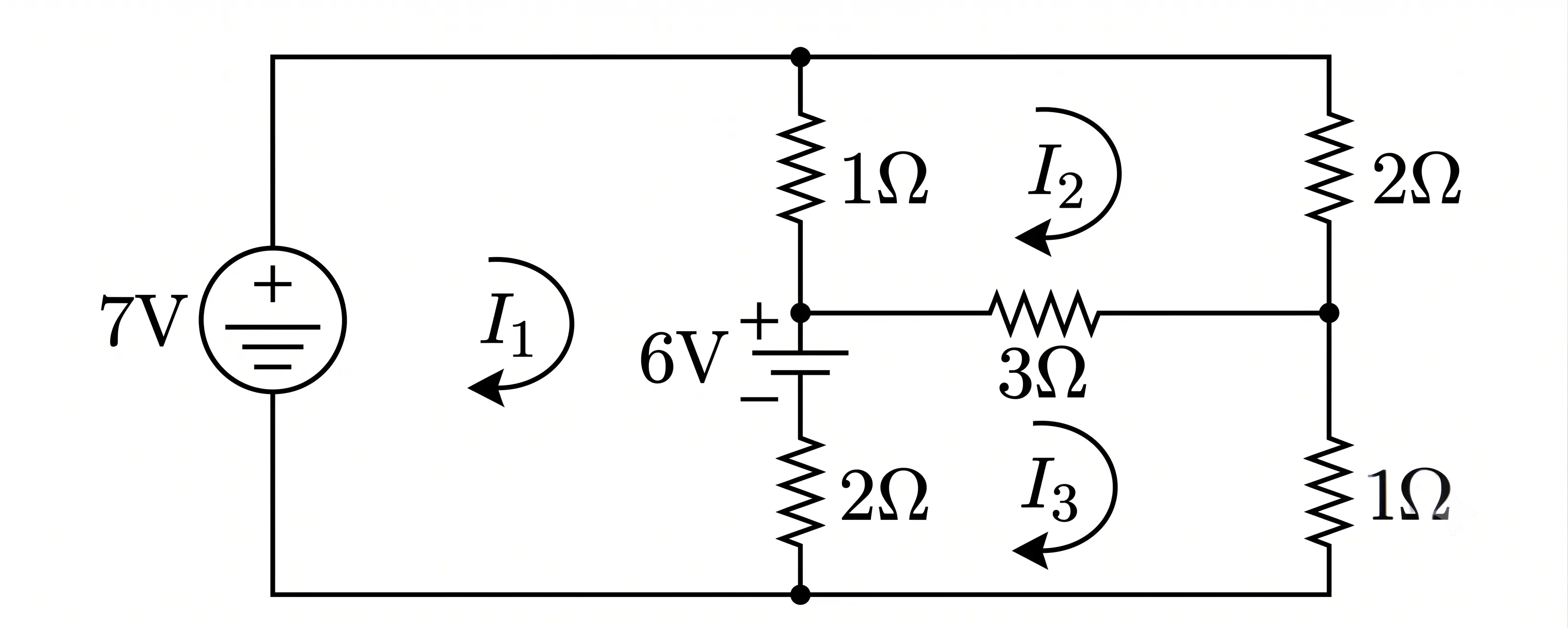
Use mesh analysis to determine the three mesh current in the circuit of the figure below.
Circuit Diagram
Figure for Question 1(a).
AI Answer Available
Click to expandExpanded
b)Unit 1
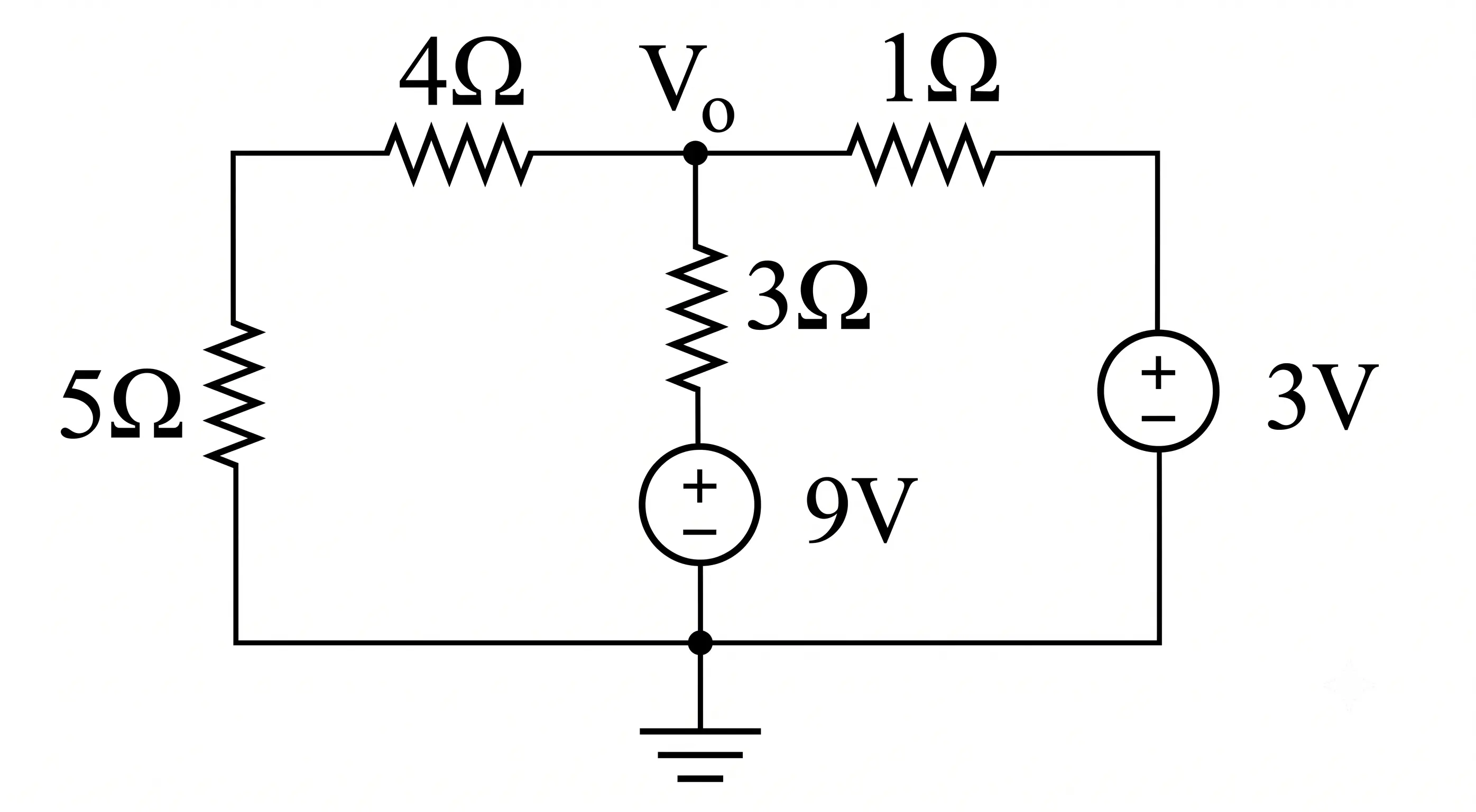
Using super position, find the V0 in the circuit shown in figure below.
Circuit Diagram
Figure for Question 1(b).
AI Answer Available
Click to expandExpanded
Q.2
a)Unit 1
Discuss about the Star Delta transformation using suitable example.
AI Answer Available
Click to expandExpanded
b)Unit 2
Explain the following terms pertaining to an A.C. wave:
i) Time period,
ii) RMS value,
iii) Average value,
iv) Form factor.
AI Answer Available
Click to expandExpanded
Q.3
a)Unit 2
A choke coil has resistance of 10 ohm and inductance of 0.05H is connected in series with an condenser of 100 µF. The whole circuit has been connected to 200 V, 50 Hz supply. Calculate:
i) Impedance,
ii) Current,
iii) Power Factor,
iv) Real Power.
AI Answer Available
Click to expandExpanded
b)Unit 2
Derive an expression of impedance, current, power factor, power in watts in RLC series circuit.
AI Answer Available
Click to expandExpanded
Q.4
a)Unit 2
Discuss about active, reactive and apparent power in series RLC circuits.
AI Answer Available
Click to expandExpanded
b)Unit 3
Discuss about magnetization characteristics of ferromagnetic material.
AI Answer Available
Click to expandExpanded
Q.5
a)Unit 3
Discuss the laws of Electromagnetic induction.
AI Answer Available
Click to expandExpanded
b)Unit 3
Open circuit and short circuit test on a single phase transformer gave the following results: V0=200V, I0=0.7A, W0=20 Watt Test from primary side. Vs=10V, Is=10A, Ws=40 Watt test from secondary side. Determine the equivalent circuit parameters referred to primary side.
AI Answer Available
Click to expandExpanded
Q.6
a)Unit 4
Draw and explain the complete Torque-slip characteristics of 3 phase induction motor.
AI Answer Available
Click to expandExpanded
b)Unit 4
The core loss in a 3 phase induction motor is 100W and equals the mechanical loss, stator copper loss is 150W. When developing 2000W as the shaft power. What is the efficiency of the machine. Assume the slip as 4%.
AI Answer Available
Click to expandExpanded
Q.7
a)Unit 5
What do you understand by Adder circuit? Draw and explain the working principle of full adder circuit.
AI Answer Available
Click to expandExpanded
b)Unit 5
In a fixed bias circuit using n-p-n transistor, find the operating point if VCC=24V, RB=220kΩ, RC=4.7kΩ.